
SUPER CONDUCTIVITY
The electrical resistivity of many metals and alloys drops suddenly to zero when the specimen is cooled to a sufficiently low temperature often a temperature in the liquid helium range. This phenomenon is called superconductivity. At a critical temperature Tc the specimen undergoes a phase transition from a state of normal electrical resistivity to a superconducting state Fig 17. This phenomenon was observed by Heike Kamerlingh Onnes in 1911.

The superconducting state is on ordered state of the conduction electrons of the metal. The order is in the formation of loosely associated pairs of electrons. The electrons are ordered at temperatures below the transition temperature and they are disordered above the transition temperature Tc.
Occurrence of superconductivity
Superconductivity occurs in many metallic elements of the periodic system and also in alloys, intermetallic compounds and doped semiconductors.
Tc values of some elements, alloys and compounds are given in table (2.2)

Electrical resistivity in Alloys
The resistivity of a pure metal increases at a particular temperature when we add more and more impurities or when we make alloy. So the resistivity of alloys depends upon the percentage of impurity material in the base material at a particular temperature.
According to Nordheim's rule, at a particular temperature, the residual or ideal resistivity of an alloy can be written as


High resistivity alloys
High resistivity alloys is made by mixing of various metals with appropriate percentage and temperature.
1. Nichrome
79.80% Ni, 19.20% Cr, 1.15% Mn and small amount of iron, used as heating elements in heaters and furnaces.
2. Manganin
86% Cu, 12% Mn and 2% Ni used as standard resistances.
3. Constantan
60% Cu and 40% Ni used as thermocouples, rheostats and starters for electric motors.
4. Kanthal
69% Fe, 23% Cr, 6% Al and 2% Co, used as heating elements in heaters and furnaces.
Conducting Materials
The choice of a conductor for a given application depends not only on its electrical conductivity, but also on various other parameters, such as corrosion resistance, mechanical strength and workability. Copper and aluminium are the most widely used high conductivity materials, of the two, copper is more widely used. Only recently is aluminium being used as a substitute, particularly in view of the increasing price of copper. Hard copper is used in bus bars, commutators segments, contact functions like switches and relays while soft copper is used for magnet wires, cable strands etc.
Copper is the most widely used material as it has (i) the highest conductivity next only to silver, (ii) can be drawn into wires, strips or rolled into sheets (iii) fairly resistant to corrosion and (iv) has good mechanical strength. Generally in electrical power utilities copper of high purity better than 99% is required, very often purity of the order of 99.9% or better is needed. The impurities present affect both electrical and mechanical properties. 0.2% of Fe or 0.3% of As brings down the conductivity to 50% as shown in Fig. 14. Here the oxygen content must be less than 0.1%. Copper with total impurity content of less than 0.5% and of oxygen less than 0.02% has excellent mechanical properties. Such copper is used to draw thin wires. The wire produced by a cold working process has light tensile strength. Annealing produces soft copper having good ductility and low hardness.

Aluminium is progressively replacing copper in many applications. The electrical resistivity of aluminium is about 1.6 times that of copper and it has about one-third the density of copper. Also, linear coefficient of expansion, specific heat and melting point are higher. In mechanical properties it is inferior to copper. For the same resistance and length of wire, aluminium has half the weight of copper. Impurities have a similar effect on the electrical resistivity as in copper. An oxide film formed on the surface of aluminium prevents further corrosion of the material.
Classification of solids on the basis of band theory
A solid is determined as a conductor, insulator or semiconductor by the energy band structure.
Conductors
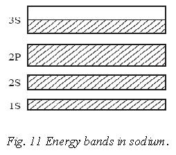
Thus if there are N atoms in a solid piece of sodium, its 3s valence band will contain N energy levels can hold 2N electrons. Thus the 3s band in sodium is only half filled by electrons and the Fermi energy EF lies in the middle of the band. When a potential difference is applied across a piece of solid sodium, 3s electrons can pick up additional energy while remaining in their original band. The additional energy is in the form of KE, and the drift of the electrons constitute an electric current. Sodium is therefore a good conductor.
Insulators

Semiconductors
Silicon has a crystal structure like diamond; a gap separates the top of its filled valence band from an empty conduction band above it. The band gap in silicon however is only about 1eV wide. At low temperature silicon is little better than diamond as a conductor, but at room temperature a small number of its valence electrons have enough thermal energy to jump the forbidden band and enter the conduction band.

These electrons, though few, are still enough to allow a small amount of current to flow when an electric field is applied. Thus silicon has a resistivity intermediate between those of conductors and those of insulators and is called as semiconductors. The energy band diagram of semiconductor is given in Fig. 13.
Band theory of solids
The energy band structure of a solid determines whether it is a conductor, an insulator or a semiconductor.
A solid contains an enormous number of atoms packed closely together. Each atom, when isolated, has a discrete set of electron energy levels 1s,2s,2p,....... If we imagine all the N atoms of the solid to be isolated from one another, they would have completely coinciding schemes of their energy levels.
Let us study what happens to the energy levels of an isolated atom, as they are brought closer and closer together to form a solid. If the atoms are brought in close proximity, the valence electrons of adjacent atoms interact. Hence the valence electrons constitute a single system of electrons common to the entire crystal with overlapping of their outermost electronic orbits. Therefore, the N electrons will now have to occupy different energy levels. This is brought about by the electric forces exerted in each electron by all the N nuclei. As a result of these forces, each atomic energy level is split up into a large number of closely spaced energy levels. A set of such closely spaced energy levels is called an energy band.
For example, the 11 electrons in a neutral sodium atom, each occupy a specific energy level as indicated in fig.10.

In the energy band, the allowed energies are almost continuous. These energy bands are in general, separated by regions, which have no allowed energy levels. These regions are known as "forbidden bands" or 'energy gaps'.
The amount of splitting is not the same for different levels. The levels filled by the valence electrons in an atom are disturbed to a greater extant, while those filled by inner electrons are disturbed only slightly fig.10.
If there are N atoms in a solid, there will be N allowed quantum states in each band. Each quantum state can be occupied by a maximum of two electrons with opposite spins. Thus each energy band can be occupied by 2N electrons. The band formed from the atomic energy levels containing valance electrons is called valance band. These electrons have the highest energy. Above the valance band, there is the band of next higher permitted energies called the 'conduction band'. The conduction band corresponds to the first excited states; electrons can move freely in this band and are called 'conduction electrons'. The interval between conduction band and valence band in which electrons cannot occupy is called 'Forbidden gap'.
A solid contains an enormous number of atoms packed closely together. Each atom, when isolated, has a discrete set of electron energy levels 1s,2s,2p,....... If we imagine all the N atoms of the solid to be isolated from one another, they would have completely coinciding schemes of their energy levels.
Let us study what happens to the energy levels of an isolated atom, as they are brought closer and closer together to form a solid. If the atoms are brought in close proximity, the valence electrons of adjacent atoms interact. Hence the valence electrons constitute a single system of electrons common to the entire crystal with overlapping of their outermost electronic orbits. Therefore, the N electrons will now have to occupy different energy levels. This is brought about by the electric forces exerted in each electron by all the N nuclei. As a result of these forces, each atomic energy level is split up into a large number of closely spaced energy levels. A set of such closely spaced energy levels is called an energy band.
For example, the 11 electrons in a neutral sodium atom, each occupy a specific energy level as indicated in fig.10.
The energy levels of sodium become bands when the atoms are close together. In figure r0 is the distance between the atoms in solid sodium. When the atoms are in solid, they interact with each other and the electrons have slightly different energies.
In the energy band, the allowed energies are almost continuous. These energy bands are in general, separated by regions, which have no allowed energy levels. These regions are known as "forbidden bands" or 'energy gaps'.
The amount of splitting is not the same for different levels. The levels filled by the valence electrons in an atom are disturbed to a greater extant, while those filled by inner electrons are disturbed only slightly fig.10.
If there are N atoms in a solid, there will be N allowed quantum states in each band. Each quantum state can be occupied by a maximum of two electrons with opposite spins. Thus each energy band can be occupied by 2N electrons. The band formed from the atomic energy levels containing valance electrons is called valance band. These electrons have the highest energy. Above the valance band, there is the band of next higher permitted energies called the 'conduction band'. The conduction band corresponds to the first excited states; electrons can move freely in this band and are called 'conduction electrons'. The interval between conduction band and valence band in which electrons cannot occupy is called 'Forbidden gap'.
Importance Of Fermi Energy:
Fermi energy of a metal separates the filled states and empty states at 0 K.
Fermi energy acts as a reference energy level. Based on its value, the number of free electrons per unit volume in a metal is determined
Therefore the electrical conductivity of a metal depends on its Fermi energy.
In explaining any physical property like electrical conductivity, thermal conductivity, specific heat, susceptibility or optical absorption only Fermi level electrons are used.
In the case of semiconductors or insulators Fermi energy level is in the band gap situated between the conduction band and valence band. Here the position of Fermi level varies with temperature and carrier concentration. Thus the value of the Fermi energy determines the electrical conductivity of semiconductors and insulators also.
Effective mass of electrons
When an electron in a periodic potential is accelerated relative to the lattice in an electric field or magnetic field, then the mass of that electron is called effective mass. Consider that an external electric field, is applied to an electron of change, q and mass, m inside the crystal.
Scott-T transformer
A Scott-T Transformer (also called a Scott Connection) is a type of circuit used to derive two-phase (2-φ) current from a three-phase (3-φ) source or vice-versa. The Scott connection evenly distributes a balanced load between the phases of the source.


The Scott-T Transformer connection may be also be used in a back to back T to T arrangement for a three-phase to 3 phase connection. This is a cost saving in the smaller kVA transformers due to the 2 coil T connected to a secondary 2 coil T in-lieu of the traditional three-coil primary to 3 coil secondary transformer. In this arrangement the X0 Neutral tap is part way up on the secondary Teaser transformer see below. The voltage stability of this T to T arrangement as compared to the traditional 3 coil primary to three-coil secondary transformer is questioned.
Nikola Tesla's original polyphase power system was based on simple to build two-phase components. However, as transmission distances increased, the more transmission line efficient three-phase system became more prominent. Both 2-φ and 3-φ components coexisted for a number of years and the Scott-T transformer connection allowed them to be interconnected.
Assuming the desired voltage is the same on the two and three phase sides, the Scott-T transformer connection (shown below) consists of a center-tapped 1:1 ratio Main transformer T1 and an 86.6% (0.5√3) ratio Teaser transformer T2. The center-tapped side of T1 is connected between two of the phases on the three-phase side. Its center tap then connects to one end of the lower turn count side of T2, the other end connects to the remaining phase. The other side of the transformers then connect directly to the two pairs of a two-phase four-wire system.
Auto-Transformer
• This is having only one winding; part of this winding is common to both primary and secondary.
• In 2-winding transformer both primary and secondary windings are electrically isolated, but this is not in the case of autotransformer.
• The operations of both the transformers are similar.
• It is cheaper than the 2-winding transformer because usage of copper is less.
• It is used where the transformation ratio is less than the unity.
• It is smaller in size but has higher efficiency and superior in voltage regulation compared to 2-winding transformer.
• In a step down autotransformer, BC is the primary winding having N1 number of turns CE is the secondary winding having N2 number of turns.
• If we apply a voltage V1 to the coil BC, alternating magnetic flux will be produced in the core

• When load is connected between terminals E and C power will be supplied to it.
Neglecting iron losses and no load current,

• The current in section CE is the vector difference of current in the section BE (I1) and load current (I2).
• Since these two currents are practically in phase opposition.
• The resultant current is (I2 – I1) where I2 is greater than I1.
Apparent power supplied to the load = V2 I2 volt-ampere
= V2 I1 + V2 (I2 – I1) VA.
Here V2I1 is the portion of the apparent power supplied to the load through the portion BE by conduction and portion V2 (I2 – I1) is the power supplied to the load through the portion CE by induction.
Advantages of Auto transformer
1. Only one winding is used in the autotransformer. Therefore weight of the core material and volume of copper required reduces which results in low cost.
2. Power losses are less. So efficiency will be high
3. Higher KVA rating
4. Lower percentage reactance. Hence better voltage regulation
5. Can be used for obtaining variable voltage supply.
Disadvantages of Auto transformer
1. In autotransformers, the high voltage winding and low voltage winding is not electrically isolated. There is a electrical connection between those two windings.
2. If there is an accidental open circuit in the low voltage winding the voltage of the high voltage winding affects the load side.
3. Short circuit current due to external short circuit in auto transformers will be twice that of short circuit current in two winding transformer.
4. As a result of higher short circuit currents, the auto transformer winding need higher mechanical strength than that of the two winding transformer.
5. Autotransformer winding need more insulation than that of two winding transformer.
Applications of auto transformer
Autotransformers are used:
1. To give small boost to a transmission line to correct the voltage drop.
2. To interconnect two grids which have different voltage ratings (3 phase auto transformers)
3. As starters for 3 phase induction motors.
4. To give smooth variation of voltage to test circuits in the laboratories.
5. As furnace transformers for getting convenient supply to suit the furnace winding from a 230 volt supply.
6. As control equipment for single phase and 3 phase electric locomotives.
All day efficiency

Large capacity transformers used in power systems are classified broadly into Power transformers and Distribution transformers. The former variety is seen in generating stations and large substations. Distribution transformers are seen at the distribution substations.
The basic difference between the two types arise from the fact that the power transformers are switched in or out of the circuit depending upon the load to be handled by them. Thus at 50% load on the station only 50% of the transformers need to be connected in the circuit. On the other hand a distribution transformer is never switched off. It has to remain in the circuit irrespective of the load connected. In such cases the constant loss of the transformer continues to be dissipated. Hence the concept of energy based efficiency is defined for such transformers. It is called 'allday' efficiency. The allday efficiency is thus the ratio of the energy output of the transformer over a day to the corresponding energy input. One day is taken as duration of time over which the load pattern repeats itself. This assumption, however, is far from being true. The power output varies from zero to full load depending on the requirement of the user and the load losses vary as the square of the fractional loads. The no-load losses or constant losses occur throughout the 24hours.Thus,the comparison of loads on different days becomes difficult. Even the load factor, which is given by the ratio of the average load to rated load, does not give satisfactory results. The calculation of the all day efficiency is illustrated below with an example. The graph of load on the transformer, expressed as a fraction of the full load is plotted against time in Fig. 27. In an actual situation the load on the transformer continuously changes. This has been presented by a stepped curve for convenience.
Hence a better option would be to keep the constant losses very low to keep the allday efficiency high. Variable losses are related to load and are associated with revenue earned. The constant losses on he other hand has to be incurred to make the service available. The concept of all day efficiency may therefore be
more useful for comparing two transformers subjected to the same load cycle. The concept of minimizing the lost energy comes in to effect right from the time of procurement of the transformer. The constant losses and variable losses are capitalized and added to the material cost of the transformer in order to select the most competitive one, which gives minimum cost taking initial cost and running cost put together. Obviously the iron losses are capitalized more in the process to give an effect to the maximization of energy efficiency. If the load cycle is known at this stage, it can also be incorporated in computation
of the best transformer.
SUMPNER’S TEST
Load Test helps to determine the total loss that takes place, when the transformer is loaded. Unlike the tests described previously, in the present case nominal voltage is applied across the primary and rated current is drown from the secondary. Load test is used mainly
1. To determine the rated load of the machine and the temperature rise
2. To determine the voltage regulation and efficiency of the transformer. Rated load is determined by loading the transformer on a continuous basis and observing the steady state temperature rise. The losses that are generated inside the transformer on load appear as heat. This heats the transformer and the temperature of the transformer increases. The insulation of the transformer is the one to get affected by this rise in the temperature. Both paper and oil which are used for insulation in the transformer start getting degenerated and get decomposed. If the flash point of the oil is reached the transformer goes up in fames. Hence to have a reasonable life expectancy the loading of the transformer must be limited to that value which gives the maximum temperature rise tolerated by the insulation. This aspect of temperature rise cannot be guessed from the electrical equivalent circuit. Further, the losses like dielectric losses and stray load losses are not modeled in the equivalent circuit and the actual loss under load condition will be in error to that extent. Many external means of removal of heat from the transformer in different cooling methods give rise to different values for temperature rise of insulation. Hence these permit different levels of loading for the same transformer. Hence the only sure way of ascertaining the rating is by conducting a load test.
It is rather easy to load a transformer of small ratings. As the rating increases it becomes difficult to find a load that can absorb the requisite power and a source to feed the necessary current. As the transformers come in varied transformation ratios, in many cases it becomes extremely difficult to get suitable load impedance.
Further, the temperature rise of the transformer is due to the losses that take place `inside' the transformer.
The efficiency of the transformer is above 99% even in modest sizes which means 1 percent of power handled by the transformer actually goes to heat up the machine. The remaining 99% of the power has to be dissipated in load impedance external to the machine. This is very wasteful in terms of energy also. ( If the load is of unity power factor) methods of loading and `Phantom' loading are commonly used in the case of transformers. The load is applied and held constant till the temperature rise of transformer reaches a steady value. If the final steady temperature rise is lower than the maximum permissible value, then load can be increased else it is decreased. That load current which gives the maximum permissible temperature rise is declared as the nominal or rated load current and the volt amperes are computed using the same.
In the equivalent loss method a short circuit test is done on the transformer. The short circuit current is so chosen that the resulting loss taking place inside the transformer is equivalent to the sum of the iron losses, full load copper losses and assumed stray load losses. By this method even though one can pump in equivalent loss inside the transformer, the actual distribution of this loss vastly differs from that taking place in reality. Therefore this test comes close to a load test but does not replace one.

In Phantom loading method two identical transformers are needed. The windings
are connected back to back as shown in Fig. 22. Suitable voltage is injected into the loop formed by the two secondaries such that full load current passes through them. An equivalent current then passes through the primary also. The voltage source V1 supplies the magnetizing current and core losses for the two transformers. The second source supplies the load component of the current and losses due to the same. There is no power wasted in a load ( as a matter of fact there is no real load at all) and hence the name Phantom or virtual loading. The power absorbed by the second transformer which acts as a load is pushed back in to the mains. The two sources put together meet the core and copper losses of the two transformers. The transformers work with full flux drawing full load currents and hence are closest to the actual loading condition with a physical load.
Per Unit Impedance Of Single Phase Transformers
Transformers of different ratings may be required to operate in parallel. If they have to share the total load in proportion to their ratings the larger machine has to draw more current. The voltage drop across each machine has to be the same by virtue of their connection at the input and the output ends. Thus the larger machines have smaller impedance and smaller machines must have larger ohmic impedance. Thus the impedances must be in the inverse ratios of the ratings. As the voltage drops must be the same the per unit impedance of each transformer on its own base, must be equal. In addition if active and reactive power is required to be shared in proportion to the ratings the impedance angles also must be the same. Thus we have the requirement that per unit resistance and per unit reactance of both the transformers must be the same for proper load sharing.
The Polarity Of Connection Of Single Phase Transformers And Its Two Cases
The polarity of connection in the case of single phase transformers can be either same or opposite. Inside the loop formed by the two secondaries the resulting voltage must be zero. If wrong polarity is chosen the two voltages get added and short circuit results. In the case of polyphase banks it is possible to have permanent phase error between the phases with substantial circulating current. Such transformer banks must not be connected in parallel. The turns ratios in such groups can be adjusted to give very close voltage ratios but phase errors cannot be compensated. Phase error of 0.6 degree gives rise to one percent difference in voltage. Hence poly phase transformers belonging to the same vector group alone must be taken for paralleling. Transformers having _30 angle can be paralleled to that having +30 angle by reversing the phase sequence of both primary and secondary terminals of one of the transformers. This way one can overcome the problem of the phase angle error. Polarity of connection The polarity of connection in the case of single phase transformers can be either same or opposite. Inside the loop formed by the two secondaries the resulting voltage must be zero. If wrong polarity is chosen the two voltages get added and short circuit results. In the case of polyphase banks it is possible to have permanent phase error between the phases with substantial circulating current. Such transformer banks must not be connected in parallel. The turns ratios in such groups can be adjusted to give very close voltage ratios but phase errors cannot be compensated. Phase error of 0.6 degree gives rise to one percent difference in voltage. Hence poly phase transformers belonging to the same vector group alone must be taken for paralleling. Transformers having _30angle can be paralleled to that having +30 angle by reversing the phase sequence of both primary and secondary terminals of one of the transformers. This way one can overcome the problem of the phase angle error.
are not the same. These are discussed now in sequence Phase sequence
The phase sequence of operation becomes relevant only in the case of poly phase systems. The poly phase banks belonging to same vector group can be connected in parallel. A transformer with +30 phase angle however can be paralleled with the one with _30 phase angle, the phase sequence is reversed for one of them both at primary and secondary terminals. If the phase sequences are not the same then the two transformers cannot be connected in parallel even if they belong to same vector group. The phase sequence can be found out by the use of a phase sequence indicator. Performance of two or more single phase transformers working in parallel can be computed using their equivalent circuit. In the case of poly phase banks also the approach is identical and the single phase equivalent circuit of the same can be used. Basically two cases arise in these problems. Case A: when the voltage ratio of the two transformers is the same and Case B: when the voltage ratios.
CASE A: Equal voltage ratios
Always two transformers of equal voltage ratios are selected for working in parallel. This way one can avoid a circulating current between the transformers. Load can be switched on subsequently to these bus bars. Neglecting the parallel branch of the equivalent circuit the above connection can be shown as in Fig. 38(a),(b). The equivalent circuit is drawn in terms of the secondary parameters. This may be further simplified as shown under Fig. 38(c). The voltage drop across the two transformers must be the same by virtue of common connection
at input as well as output ends. By inspection the voltage equation for the drop can be


From the above it is seen that the transformer with higher impedance supplies lesser load current and vice versa. If transformers of dissimilar ratings are paralleled the transformer with larger rating shall have smaller impedance as it has to produce the same drop as the other transformer, at a larger current. Thus the ohmic values of the impedances must be in the inverse ratio of the ratings of the transformers.
(IAZA = IBZB ) and IA//IB = ZB /ZA
.
Expressing the voltage drops in p.u basis, we aim at the same per unit drops at any load for the transformers. The per unit impedances must therefore be the same on their respective bases. Fig. 39 shows the phasor diagram of operation for these conditions. The drops are magnified and shown to improve clarity. It is seen that the total voltage drop inside the

transformers is v but the currents IA and IB are forced to have a different phase angle due to the difference in the internal power factor angles IA and IB. This forces the active and reactive components of the currents drawn by each transformer to be different ( even in the case when current in each transformer is the same). If we want them to share the load current in proportion to their ratings, their percentage ( or p.u) impedances must be the same. In order to avoid any divergence and to share active and reactive powers also properly, φA = φB. Thus the condition for satisfactory parallel operation is that the p.u resistances and p.u reactance must be the same on their respective bases for the two transformers. To determine the sharing of currents and power either p.u parameters or ohmic values can be used.
CASE-B UNEQUAL VOLTAGE RATIO

One may not be able to get two transformers of identical voltage ratio in spite of ones best efforts. Due to manufacturing differences, even in transformers built as per the same design, the voltage ratios may not be the same. In such cases the circuit representation for parallel operation will be different as shown in Fig. 40. In this case the two input voltages cannot be merged to one, as they are different. The load brings about a common connection at the output side. EA and EB are the no-load secondary emf. ZL is the load impedance at the secondary terminals. By nspection the voltage equation can be written as below:
EA = IAZA + (IA + IB)ZL = V + IAZA
EB = IBZB + (IA + IB)ZL = V + IBZB (95)
Solving the two equations the expression for IA and IB can be obtained as


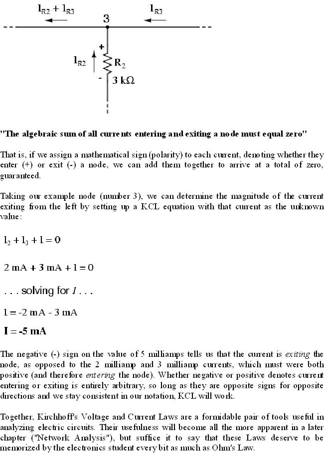
Kirchhoff's Current Law (KCL)

The current entering any junction is equal to the current leaving that junction. i1 + i4 = i2 + i3
This law is also called Kirchhoff's first law, Kirchhoff's point rule, Kirchhoff's junction rule (or nodal rule), and Kirchhoff's first rule.
Let's take a closer look at that last parallel example circuit:

Solving for all values of voltage and current in this circuit:

What are "series" and "parallel" circuits?
Circuits consisting of just one battery and one load resistance are very simple to analyze, but they are not often found in practical applications. Usually, we find circuits where more than two components are connected together.
There are two basic ways in which to connect more than two circuit components: series and parallel. First, an example of a series circuit:

Here, we have three resistors (labeled R1, R2, and R3), connected in a long chain from one terminal of the battery to the other. (It should be noted that the subscript labeling -- those little numbers to the lower-right of the letter "R" -- are unrelated to the resistor values in ohms. They serve only to identify one resistor from another.) The defining characteristic of a series circuit is that there is only one path for electrons to flow. In this circuit the electrons flow in a counter-clockwise direction, from point 4 to point 3 to point 2 to point 1 and back around to 4.
Now, let's look at the other type of circuit, a parallel configuration:

The defining characteristic of a parallel circuit is that all components are connected between the same set of electrically common points. Looking at the schematic diagram, we see that points 1, 2, 3, and 4 are all electrically common. So are points 8, 7, 6, and 5. Note that all resistors as well as the battery are connected between these two sets of points.
And, of course, the complexity doesn't stop at simple series and parallel either! We can have circuits that are a combination of series and parallel, too:

This is just a preview of things to come. Don't worry! We'll explore all these circuit configurations in detail, one at a time!
The basic idea of a "series" connection is that components are connected end-to-end in a line to form a single path for electrons to flow:

The basic idea of a "parallel" connection, on the other hand, is that all components are connected across each other's leads. In a purely parallel circuit, there are never more than two sets of electrically common points, no matter how many components are connected. There are many paths for electrons to flow, but only one voltage across all components:

Series and parallel resistor configurations have very different electrical properties. We'll explore the properties of each configuration in the sections to come.
REVIEW:
• In a series circuit, all components are connected end-to-end, forming a single path for electrons to flow.
• In a parallel circuit, all components are connected across each other, forming exactly two sets of electrically common points.
• A "branch" in a parallel circuit is a path for electric current formed by one of the load components (such as a resistor).
DENSITY OF STATES:
The number of states per unit volume of the crystal which are contained in the energy interval between E and E+dE defines a density of states Z(E).
The Fermi function does not gives us the number of electrons which have certain energy. It gives us only the probability of occupation of an energy state by a single electron. In a small energy interval dE there are many discrete energy levels. So the concept of density of state is introduced to calculate the number of electrons with a given energy. By multiplying the number of states by probability occupation we get the actual number of electrons.
If N(E) is the number of electrons in a system that have energy E and Z(E) is the number of states at that energy, then
N(E) dE = Z(E) p(E) (48)
The number of energy states, with a particular value of E, depends on how many combinations of the quantum number results in the same value of n. Since we are dealing with almost a continuum of energy levels, we may construct a space of points represented by the values of nx, ny and nz and let each point with integer values of the coordinate represent an energy state.


Electron energy in metal and Fermi energy:
If we consider the three dimensional metal, electrons will move in all directions so that three quantum numbers n x, n y, n z are needed. Let us assume the potential energy inside the cubic crystal with side 'a' is zero and infinity at outside.
Therefore the permitted energy levels can be written as from equation (42).


Fig. 6 The Fermi distribution curve
Application of Schrodinger wave equation: Electron in an infinitely deep potential well (one dimension):
Consider an electron placed in an infinitely deep potential well with width 'a'. It is assumed that the movement of the electron is restricted by the walls and the electron is moving only in the x-direction. The collision of electrons with walls is perfectly elastic. Since the electron is moving freely, inside the well its potential energy V = 0 and V = outside the well so electron cannot escape from the well through the sides.


Simple Series Circuits
Let's start with a series circuit consisting of three resistors and a single battery:

The first principle to understand about series circuits is that the amount of current is the same through any component in the circuit. This is because there is only one path for electrons to flow in a series circuit, and because free electrons flow through conductors like marbles in a tube, the rate of flow (marble speed) at any point in the circuit (tube) at any specific point in time must be equal.
From the way that the 9 volt battery is arranged, we can tell that the electrons in this circuit will flow in a counter-clockwise direction, from point 4 to 3 to 2 to 1 and back to 4. However, we have one source of voltage and three resistances. How do we use Ohm's Law here?
An important caveat to Ohm's Law is that all quantities (voltage, current, resistance, and power) must relate to each other in terms of the same two points in a circuit. For instance, with a single-battery, single-resistor circuit, we could easily calculate any quantity because they all applied to the same two points in the circuit:


Since points 1 and 2 are connected together with wire of negligible resistance, as are points 3 and 4, we can say that point 1 is electrically common to point 2, and that point 3 is electrically common to point 4. Since we know we have 9 volts of electromotive force between points 1 and 4 (directly across the battery), and since point 2 is common to point 1 and point 3 common to point 4, we must also have 9 volts between points 2 and 3 (directly across the resistor). Therefore, we can apply Ohm's Law (I = E/R) to the current through the resistor, because we know the voltage (E) across the resistor and the resistance (R) of that resistor. All terms (E, I, R) apply to the same two points in the circuit, to that same resistor, so we can use the Ohm's Law formula with no reservation.
However, in circuits containing more than one resistor, we must be careful in how we apply Ohm's Law. In the three-resistor example circuit below, we know that we have 9 volts between points 1 and 4, which is the amount of electromotive force trying to push electrons through the series combination of R1, R2, and R3.
However, we cannot take the value of 9 volts and divide it by 3k, 10k or 5k Ω to try to find a current value, because we don't know how much voltage is across any one of those resistors, individually.


REVIEW:
• Components in a series circuit share the same current: ITotal = I1 = I2 = . . . In
• Total resistance in a series circuit is equal to the sum of the individual resistances: RTotal = R1 + R2 + . . . Rn
• Total voltage in a series circuit is equal to the sum of the individual voltage drops: ETotal = E1 + E2 + . . . En
The first principle to understand about series circuits is that the amount of current is the same through any component in the circuit. This is because there is only one path for electrons to flow in a series circuit, and because free electrons flow through conductors like marbles in a tube, the rate of flow (marble speed) at any point in the circuit (tube) at any specific point in time must be equal.
From the way that the 9 volt battery is arranged, we can tell that the electrons in this circuit will flow in a counter-clockwise direction, from point 4 to 3 to 2 to 1 and back to 4. However, we have one source of voltage and three resistances. How do we use Ohm's Law here?
An important caveat to Ohm's Law is that all quantities (voltage, current, resistance, and power) must relate to each other in terms of the same two points in a circuit. For instance, with a single-battery, single-resistor circuit, we could easily calculate any quantity because they all applied to the same two points in the circuit:
Since points 1 and 2 are connected together with wire of negligible resistance, as are points 3 and 4, we can say that point 1 is electrically common to point 2, and that point 3 is electrically common to point 4. Since we know we have 9 volts of electromotive force between points 1 and 4 (directly across the battery), and since point 2 is common to point 1 and point 3 common to point 4, we must also have 9 volts between points 2 and 3 (directly across the resistor). Therefore, we can apply Ohm's Law (I = E/R) to the current through the resistor, because we know the voltage (E) across the resistor and the resistance (R) of that resistor. All terms (E, I, R) apply to the same two points in the circuit, to that same resistor, so we can use the Ohm's Law formula with no reservation.
However, in circuits containing more than one resistor, we must be careful in how we apply Ohm's Law. In the three-resistor example circuit below, we know that we have 9 volts between points 1 and 4, which is the amount of electromotive force trying to push electrons through the series combination of R1, R2, and R3.
However, we cannot take the value of 9 volts and divide it by 3k, 10k or 5k Ω to try to find a current value, because we don't know how much voltage is across any one of those resistors, individually.
REVIEW:
• Components in a series circuit share the same current: ITotal = I1 = I2 = . . . In
• Total resistance in a series circuit is equal to the sum of the individual resistances: RTotal = R1 + R2 + . . . Rn
• Total voltage in a series circuit is equal to the sum of the individual voltage drops: ETotal = E1 + E2 + . . . En
Subscribe to:
Posts (Atom)