1. PREFACE
Every PC has one or more LPT printer parallel port adapter. This adapter have several I/O port. In old PC, the parallel port may be set at video adapter card or at separate I/O device card (multi I/O). In the beginning, this port only used for printer device, so the data port (8 bits) only used for sending data to the printer and can not receive data from the outside. Now, everything has changed. Many device were connected to this parallel port, so the design always change time to time, even the characteristic always the same (i.e. new card usually used a new chip design and have more capabilities, like bidirectional data transfer, can be configured to work more faster, etc., etc.). Ok, lets we explore more about it now.
2. SIGNAL NAME & PURPOSE
Because the parallel port have many location, so the port also follow this procedure and always standard. For our description, DP refer to printer Data Port, PC refer to Printer Control and PS refer to Printer Status. Tabel-1 shown each port and their function.
| LPT 0 | LPT 1 | LPT 2 | Operation | Description |
| 3BC Hex | 378 Hex | 278 Hex | (Read)/Write | Data Port (DP), 8 bits |
| 3BD Hex | 379 Hex | 279 Hex | Read only | Printer Status (PS), 5(6) bits |
| 3BE Hex | 37A Hex | 27A Hex | Read/Write | Printer Control (PC), 4(6) bits |
a. Data Port (DP)
DP has 8 bits length. It means that it can be transfer or sending data 8 bits long at a moment time. The old PC has LPT parallel port function only for sending data. Many devices nowadays have attached to this port and can work bidirectional. For examples : scanner device, many storage device like zip drive, etc., etc. This means that this port can be used for sending or receiving data. New card can be configured to work like this (eg:bi-directional port), but old one don't. In the end of this article, you can change the ability of the old card, so that it can be used to receive data. Data bits are naming as DP-0 trought DP-7. For the relation number to the D-25 socket refer to the LPT Connector. DP port can sink 24 mA at logic 0 and can source 2.6 mA at logic 1. Notice that the external device don't try to pull these DP lines to ground for a long period. The latch IC could be burn.
b. Printer Control (PC)
PC is used for controlling the function of printer. Only 4 bits used by printer and 1 bit used for interrupt enable flag. The complete description was shown on Figure-1. The interrupt enable bit flag used for handshake operation between computer and printer, so that the device can work with a little time of CPU to interfere. The most important things must be taken if you connect your own device are : the PC-0, PC-1 and PC-3 logic are inverting at socket connector terminal. This means that, when you send logic 1 (high) to this related bit, the logic output terminal is 0 (low). The PC-2 and PC-4 are normal. The PC-5 to PC-7 are not used by the hardware circuit. Note that, PC-4 bit only for the adapter card function. This means this bit does not connect out to the connector terminal. PC port can sink 7 mA at logic 0 and can source 0.6 mA at logic 1. Besides that, in some PC/AT's LPT adapter card, bit PC-5 is used for control direction (and also in bi-directional card). It means that, if this bit is high, DP port can act as input port, the latch output is tri-state. Data from outside can be read from DP port.
c. Printer Status (PS)
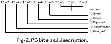
PS port used for feedback signal from printer to the computer. Only 5 MSB bits are used, the 3 LSB bits not used. The complete description was shown on Figure-2. Only 1 bit is inverting input ie. PS-7 use for busy signal. PS-6 bit use for acknowledge signal This signal used when the printing goes on with interrupt handshake operation. This is a hardware interrupt. In some PC/AT's card and bi-directional card, PS-2 is used to reflex the state of IRQ, weather it is on or off state. This bit only for internal use.
3. CONNECTOR TERMINAL
LPT port adapter use a female DB-25 D-shell connector type. The complete connection can be seen in Figure-3. Only 17 terminals be used, and the rest are grounded all. This is a standard terminal connection. The connection are the same for all of the LPT's connector. Figure-4. show the connection between printer to the LPT adapter.
4. PRINTER INTERFACE DESCRIPTION
LPT printer parallel interface in PC computer type have specification like this :
- Data transfer rate : 1000 cps (maximum)
- Synchronization : by externally-supplied STROBE pulses.
- Handshaking -ACK or +BUSY signals.
- Logic level : input data and all interface control signal are compatible with the TTL level.
STROBE pulse to read data in. Pulse width must be more than 0.5 us at receiving terminal. The signal level normally high. Read in of data is performed at the low level of this signal. ACK signal is approximately 5 us pulse. Logic low indicates that data has been received and the printer is ready to accept other data. BUSY signal high indicates that the printer can not receive data. This signal becomes high in the following cases :
- During data entry
- During printing operation
- In offline state
- During printer error status


No comments:
Post a Comment