- The tuned circuit oscillators are good for generating high frequency. oscillations.
- For low frequencies, R-C oscillators are more suitable.
- Tuned circuit is not a essential requirement for oscillation. The essential requirement is that there must be a 1800 phase shift around the feedback network and loop gain should be greater than unity.
- The 180° phase shift in feedback signal can be achieved by a suitable RC network consisting of three RC sections as shown below.
- When a sinusoidal voltage of frequency f is applied to a circuit consisting of resistor R and capacitor C in series, then the alternating current in the circuit leads the applied voltage by certain angle known as phase angle.
- The value of R and C may be selected in such a manner that for the frequency f, the phase angle is 60°.
- So using a ladder network of three R-C sections, desired 180° phase shift may be produced.
CIRCUIT ARRANGEMENT:
- The circuit arrangement of a phase shift oscillator using NPN transistor in common-emitter configuration is shown below.
- Here R — R provide dc emitter bias.
- RL is the load which controls the collector voltage. Re-Ce combination provides temperature stability and prevents ac signal degeneration.

- The output of the amplifier goes to a feedback netwok which conists of three identical R-C sections.
- It should be remembered that the last section contains a resistance R=Rhie.
- Since, this resistor is connected with the base of the transistor, the input resistance hie of the transistor is added to it to give a total resistance.
CIRCUIT ACTION:
- Here R-C network produces a phase shift of 1800 between input and output voltages.
- Since C-E amplifier produces a phase of 180°, the total phase change becomes 360° or 00 which is the essential requirement of sustáined oscillations.
- The RC phase shift networks serve as frequency determining circuit.
- Since only at a single frequency the net phase shift around the loop will be 360° a sinusoidal waveform at this frequency is generated.
- These oscillators are used for audio frequency ranges LC tuned circuits at low frequencies become too much bulky and expensive moreover they suffer from frequency instability and poor waveform.
FREQUENCY OF OSCILLATIONS:
The equivalent circuit is shown below:
The equivalent circuit can be simplified by making the following assumptions:
1. 1/hoe is much larger than RL, its effect can be neglected.
2. hre of the transistor is usually small and hence h is omitted from the circuit.
3. In practice RL is taken equal to R.
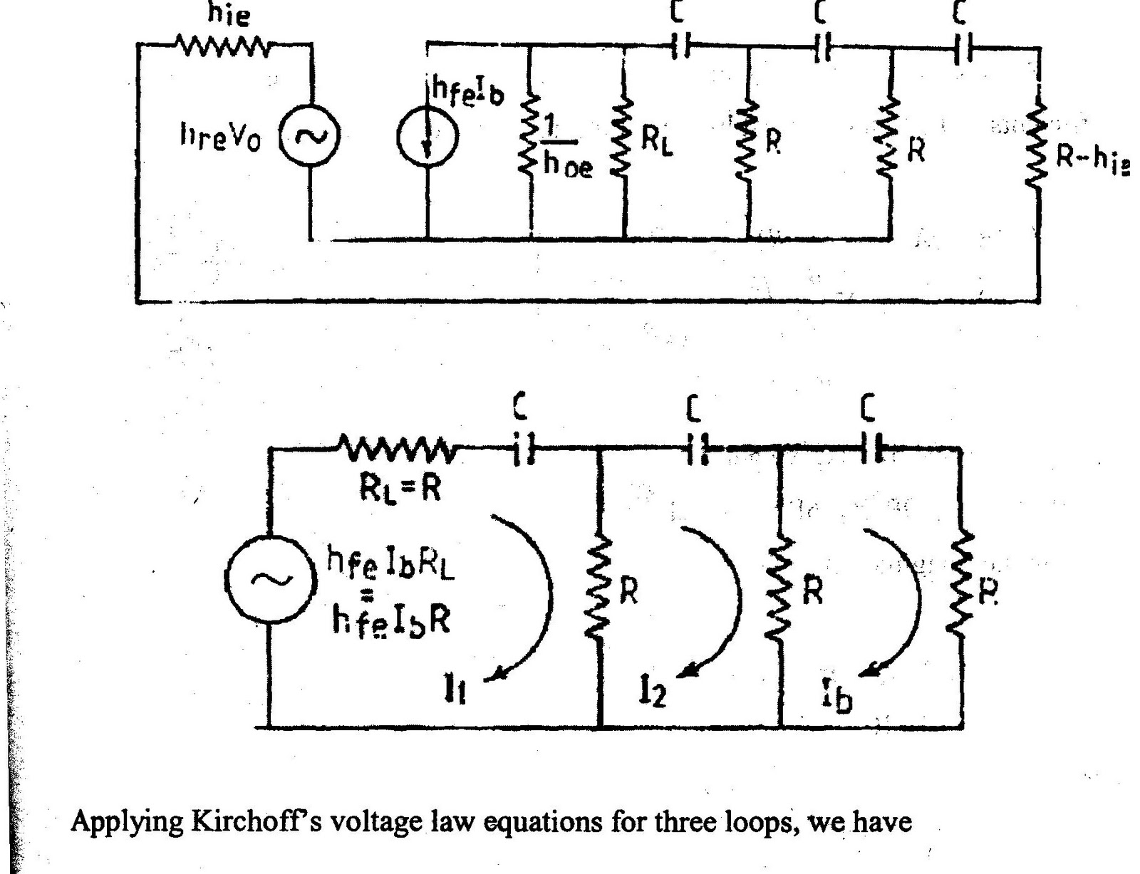


4. The current source is replaced by voltage source using Thevenin’s theorem. The simplified equivalent circuit in also shown above.
Thus for sustained oscillation, the value of hfe of transistor should be 56.
TWIN T NETWORK:
- The twin “T” network is one of the few RC filter networks capable of providing infinitely deep notch.
- By combining the twin “T” with an operational amplifier voltage follower, the usual drawbacks of the network are overcome.
- The Quality factor is raised from the usual 0.3 to something greater than 50.
- Further, the voltage folllower acts as a buffer, providing a low output resistance; and the high input resistance of the op amp makes it possible to use large resistance values in the “T” so only small capacitors are required, even at low frequencies.
- The fast response of follower allows the notch to be used at high frequencies.
- Neither the depth of the h nor the frequency of the notch are changed when the follower is added .
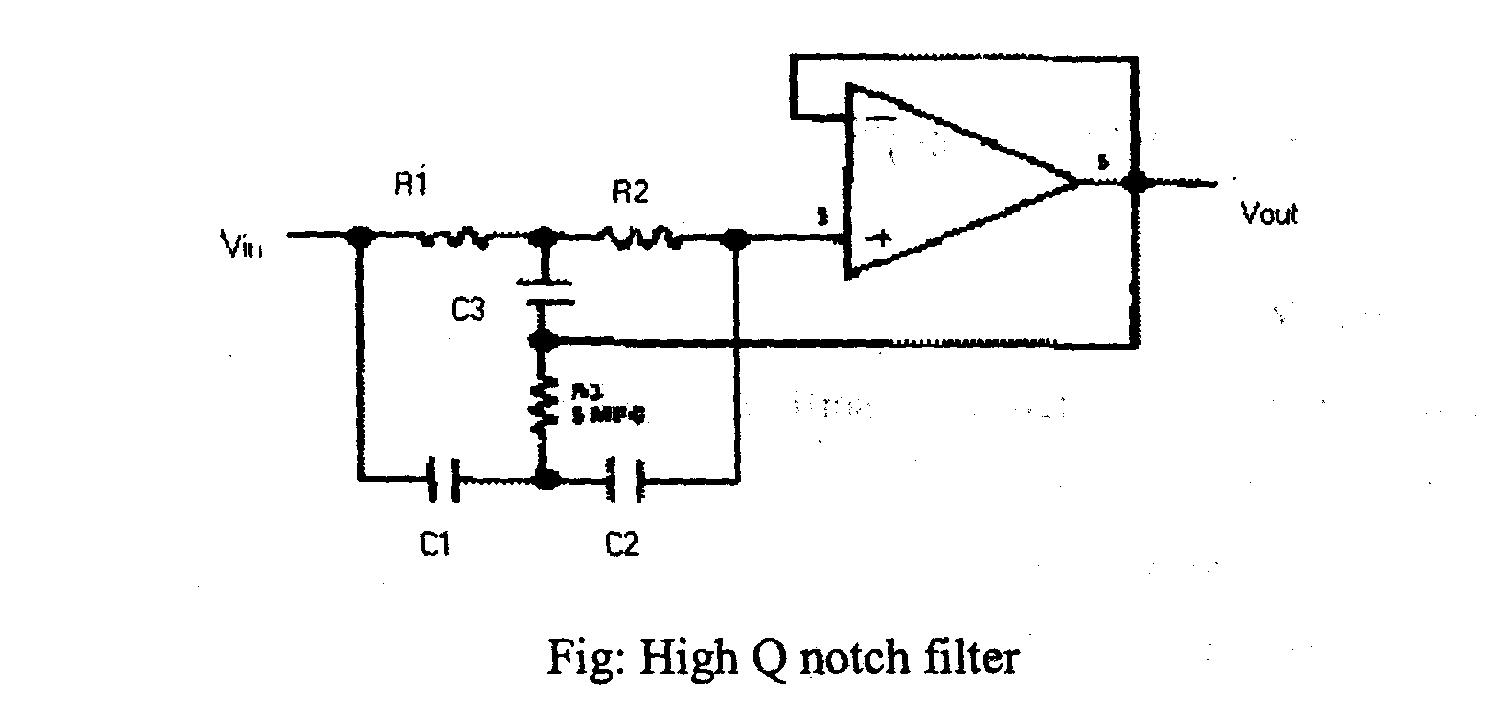
- Figure low shows a twin T” network connected to an op amp to form a high Q,60 Hz notch.
- The junction of R3 and C3, which is normally connected to ground, i bootstrapped to the output of the follower.
- Because the output of the follower is I very low impedance, neither the depth nor the frequency of the notch chang however, the Q is raised in oportion to the amount of si fed back to R3 ai C3.
- Figure below shows the response of a normal twin “T” and the response wi the follower added.

ADJUSTABLE TWIN T:
- In applications where the rejected signal-might deviate slightly from the null of the notch network, it is advantageous to lower the Q of the network.
- This insures some rejection over a wider range of input frequencies.
- Figure below shows circuit Where the Q may be varied from 0.3 to 50.
- A fraction of the output is fed back to R3 and C3 by a second voltage follower, and the Q is dependent on the amount of signal fed back.
- A second follower is necessary to drive the twin from a low-resistance source so that the notch frequency and depth will not change with the potentiometer setting.
- Depending on the potentiometer (RL) setting, the circuit in Figure, will have a response that falls in the shaded area of the frequency response plot.

- An interesting change in the high Q twin “T” occurs when components are not exactly matched in ratio.
- For example, an increase of 1 to 10 percent in the value of C3 will raise the Q, while degrading the depth of the notch.
- If the value of C3 is raised by 1,0 to 20 percent, the network provides voltage gain and acts as a tuned amplifier.
- A voltage gain of 400 was, obtained during testing.
- Further increases in C3 cause the circuit to oscillate, giving a clipped sine wave output.
- The circuit is easy to use and only a few items need be considered for proper operation.
- To minimize notch frequency shift with temperature, silver mica, or polycarbonate, capacitors should be used with precision resistors.
- Notch depth depends on component match, therefore,. 0.1 percent resistors and 1 percent capacitors are suggested to minimize the trimming needed for a 60 dB notch.
- To insure stability of the op amp, the power supplies should be bypassed near the integrated circuit package with .01 mF disc capacitors.
No comments:
Post a Comment